
Contents
Metalworking workshops often need machinery that can create accurate holes repeatedly while handling substantial workloads. Geared-head drilling machines are built around that requirement, using a mechanical gear transmission to deliver spindle drive for demanding drilling operations.
Unlike lighter bench drills, industrial geared-head machines are designed as substantial workshop equipment, with larger capacities, powered feeds and features intended for sustained metalworking. A gear head mill drill selection is a closely related space, combining drilling and milling functions.
That distinction matters: geared head drills are primarily drilling machines, while a true mill drill is intended to provide controlled material removal in both drilling and milling operations. Understanding which operation is actually required prevents paying for capability that will not be used or, conversely, expecting a drill to perform milling work for which it was not designed.
A Closer Look at Geared-Head Milling
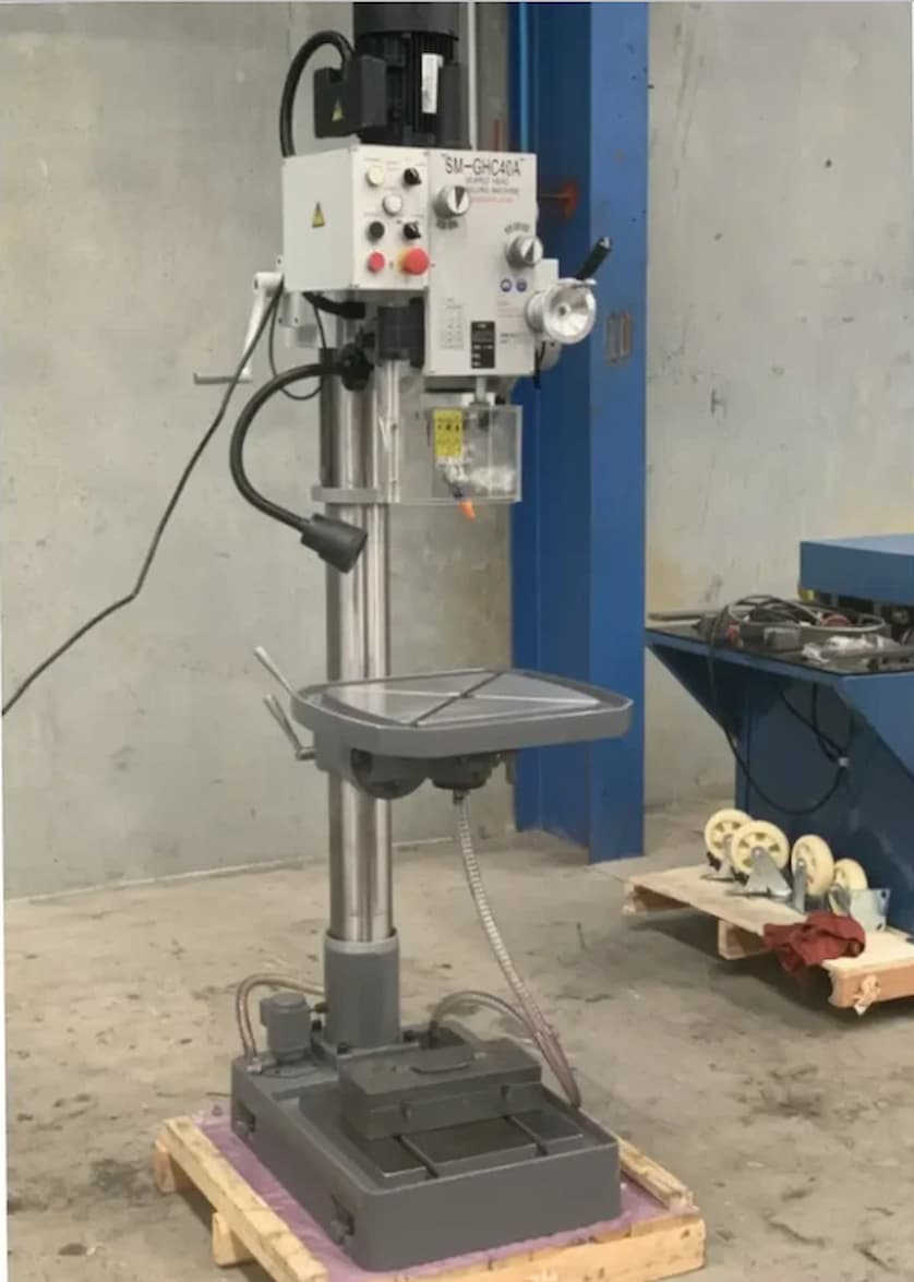
The defining feature of a geared-head mill drill is its geared drive system. Instead of relying solely on belt changes to transmit motion, gears provide direct mechanical drive between the motor and spindle. This construction is associated with robust torque delivery and makes geared machines well-suited to metalworking where larger drill sizes or heavier cutting loads are involved.
The machines in this industrial range demonstrate the scale of equipment available, with drilling capacities extending from 40 mm to 55 mm. Some configurations also incorporate power feed and coolant, while electrical versions include either 240 V or 415 V arrangements.
These are not interchangeable details: the required supply must agree with the workshop’s electrical infrastructure and the machine specification. By replacing friction belts with precision-cut gears, investing in a gear head mill drill eliminates drive slipping during high-resistance tapping and heavy pocketing operations.
Capacity, Control and the Numbers
Drilling capacity is one of the clearest starting points, but it should never be considered alone. A stated 40 mm or 55 mm capacity indicates the maximum drilling capability under specified conditions; actual performance depends on the material, cutter, cutting speed, feed and setup. A machine’s working envelope also determines how comfortably larger workpieces can be positioned.
Rather than depending entirely on an operator to maintain manual feed pressure, a powered table or quill feed can provide a more consistent movement during suitable operations. Coolant provision can assist with heat management and chip removal, particularly during prolonged cutting, although the appropriate coolant and application method depend on the material and tooling.
Shaping the Machining Process
The practical value of these machines lies in how their features work together. A geared transmission provides the mechanical drive; power feed can reduce the need for continuous manual movement; coolant equipment supports cutting processes that generate substantial heat; and digital displays can make machine settings easier to monitor.
Where a table is included in the machine configuration, it can provide a broader platform for positioning and securing work. The electrical configurations also illustrate an important industrial consideration.
A 240V machine and a 415V machine should not be treated as simply different versions of the same purchase. Voltage, phase requirements, available circuits and installation arrangements need to be confirmed before the machine reaches the workshop floor.
These machines can also be part of a wider machining workflow involving work-holding equipment, drilling and reaming tools, milling cutters and measuring equipment. The machine itself is only one part of the process; accurate work depends on suitable tooling, secure workholding and correct cutting parameters.
Before It Joins the Workshop Floor
- Confirm the electrical arrangement before ordering, including the required voltage and the workshop’s available supply, so installation does not become an afterthought.
- Evaluate capacity against the actual workpiece range rather than treating maximum drilling diameter as the only measure of capability; consider the material, hole sizes, workpiece dimensions and frequency of use together.
- Allow for the machine’s complete working footprint, including space needed to position material, operate controls and carry out routine cleaning and maintenance.
- Match cutting tools and operating parameters to the material being machined; Spindle speed and feed should be established based on appropriate tooling and material guidance.
- Plan for secure work holding and routine maintenance; clean working surfaces, properly maintained moving parts and securely mounted workpieces all contribute to controlled machining.
A Solid Foundation for Workshop Capability
For industrial drilling, the attraction of geared-head machinery is its combination of mechanical drive, substantial drilling capacity and workshop-oriented features. The range represented here extends from 40 mm to 55 mm drilling capacity and includes configurations with power feed, coolant, digital display and different electrical requirements.
A geared head mill drill can be useful where drilling and milling are genuinely required, but a geared-head drill should not automatically be described as a mill drill simply because it is robust or has a substantial table. For a workshop focused on drilling, a dedicated geared-head machine may be the more appropriate arrangement; where milling is part of the workload, the machine must specifically be designed and specified for it.

Comments are closed.